CERAMIC ARCHITECTURES AS MODELS FOR 3D PRINTED TISSUE ENGINEERING APPLICATIONS
Authors:
Marián Janek 1,2; Peter Veteška 2; Kristína Randová 2; Zora Hajdúchová 2; Katarína Tomanová 1,3; Jozef Feranc 3; Roderik Plavec 3; Leona Omaníková 3; Eva Smrčková 1; Pavel Alexy 3; Ľuboš Bača 1
Authors‘ workplace:
Department of Inorganic Materials, Faculty of Chemical and Food Technology, Slovak University of Technology, Bratislava, Slovakia
1; Department of Physical and Theoretical Chemistry, Faculty of Natural Sciences, Comenius University, Bratislava, Slovakia
2; Department of Plastics, Rubber and Fibbers, Faculty of Chemical and Food Technology, Slovak University of Technology, Bratislava, Slovakia
3
Published in:
Lékař a technika - Clinician and Technology No. 1, 2019, 49, 31-35
Category:
Overview
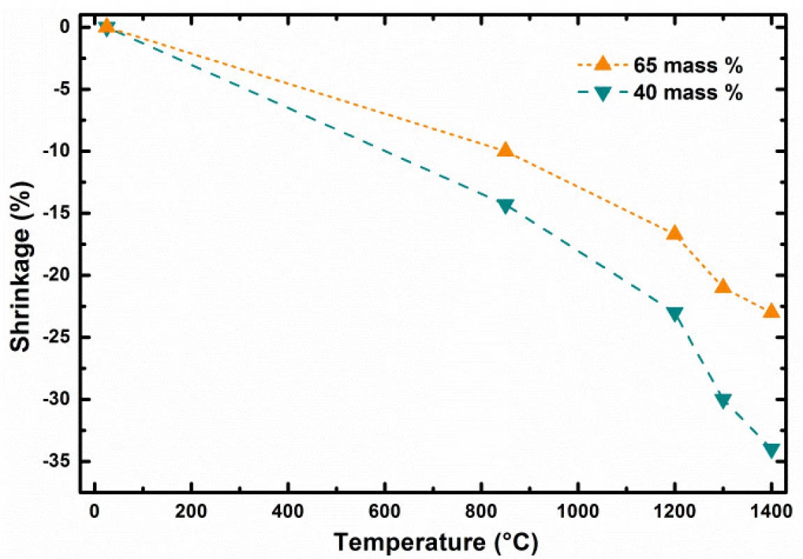
Shrinkage of ceramic objects produced by Fused Depositon Ceramics 3D printing technology was studied as model procedure for production of biocompatible scaffolds. The formulation of ceramic composite filament tested was based on components such as aluminium and silicium oxides and thermoplastic polymer. The resulting ceramic material after sintering is approaching the chemical composition of the mullite ceramics, which has several interesting material properties. The shrinkage of the produced testing objects was studied as function of the particle content in starting composite and sintering temperature. Observed shrinkage of the ceramic bodies produced was on the level of 17% for 65 weight % and the 23% for 40 weight % of inorganic filler content at temperature 1200 °C, respectively, with well maintained shape. The tested ceramic scaffolds were produced using slice thickness of 0.50 mm and fill gap of 0.58 mm, with regular rectilinear infill pores generated by Slic3r.
Introduction
Biocompatible scaffolds produced by 3D printing technologies were currently proved to be promising patient-friendly replacements respecting individual spe-cific biological shape individualities and excellent on place availability for the surgery utilization in the future. Their easy on-site availability and production can significantly improve chances of accident and/or arthro-plasty joint revision, tumor patients, war zone victims’ replacements, for their good and functional recovery and tissue regeneration after surgical operation. The tissue scaffolds for these types of operation are the hard bone replacements based on biocompatible hydroxyapatite (HAp) [1–3].
The low-cost fused deposition ceramics (FDC) technique requires the HAp to be mixed with a 3D-printable thermoplastic and biocompatible polymer such as polylactic acid (PLA). However, for enhanced bio-activity of the substitute, it is important to produce high HAp-loaded 3D-printable filaments. The known HAp filaments have usually non desired brittle nature at HAp content above 50% of fillings, which is required for good osteoconductive and osteointegration properties. Therefore, an optimized chemical composition and 3D printing processing technology are continually investi-gated by the researcher teams [4–7].
From these reasons we have investigated a mullite based ceramics prepared from filament with solid content of 40 and 65 weight % as model system for low-cost FDM (Fused Deposition Modeling) technology. It is well known that mullite (3Al2O3∙2SiO2) has good chemical and thermal stability, low thermal expansion coefficient, good fracture toughness, bending strength and others properties. In addition, the SiO2 is a typical component which improves the scaffold biocompati-bility along with oxides containing biologically active components such as CaO, Na2O and/or K2O [8–11]. Due to the fact that shrinkage of ceramic materials during their firing and sintering is their inherent behavior, the main objective of the presented study was to investigate the effect of temperature and composite filling extend on their ability to produce mullite based ceramic from filaments having new applicable formulations.
Methods
3D Printing Process
The filament having diameter of 1.75 mm was prepared by extrusion of inorganic/organic composite material using single screw extruder. A set of defined green bodies of circular shape with aspect ratio (diameter/height) equal to 5 was printed on commercial FDM 3D printer Leapfrog Creatr™ (Leapfrog 3D printers, Netherlands) with rectilinear infill according to parameters as shown in the Fig. 1. Estimated green body road width (RW) was about 0.67 ± 0.02 mm and infill road gap (RG) about 0.58 ± 0.02 mm produced after default extrusion using Slic3r (open-source software, Slic3r.org) set on infill density at the level of 35%, using the nozzle diameter 0.6 mm. The nozzle temperature (NT) was set to 215 °C, 1st road height (1RH) to 0.75 mm while the slice height of the following roads (RH) was set to 0.70 mm. The temperature of heated bed (HB) was set to 55 °C (Fig. 1).
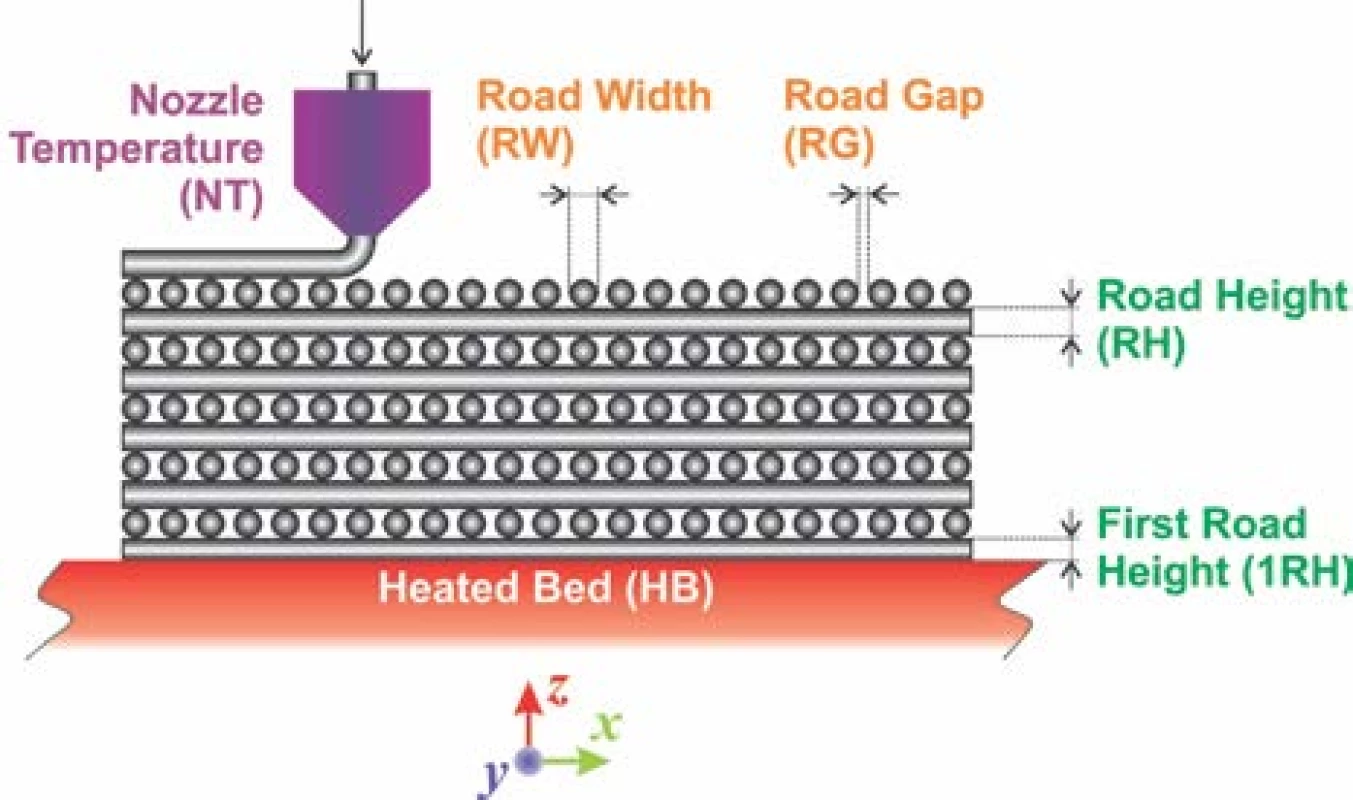
It must be emphasized that only selected printing parameters such as 1RH and subsequent RH´s are common adjustable parameter in Slic3r or similar soft-ware for FDM 3D printers available. The RW depends intrinsically on nozzle diameter, extrusion velocity and inherently includes polymer expansion coefficient. It is as well inversely proportional to value entered for RH. For the biocompatible scaffolds production it is essential achievement of bimodal pore size distribution. Such distribution should mimic pore sizes in real bones, where average pore diameters at the level of mesopores, hence below 50 nm and macropores, above 100 µm can be found. From these dimension values it is clear, that an empirical estimation of RW and RG based on selection of infill density must be experimentally verified to produce the pores with diameter ~100 µm. However, the pore sizes ~50 nm can be achieved by the selection of appropriate inorganic biocompatible material only, such as HAp with sufficiently suitable internal pore structure [12,13].
Experimental
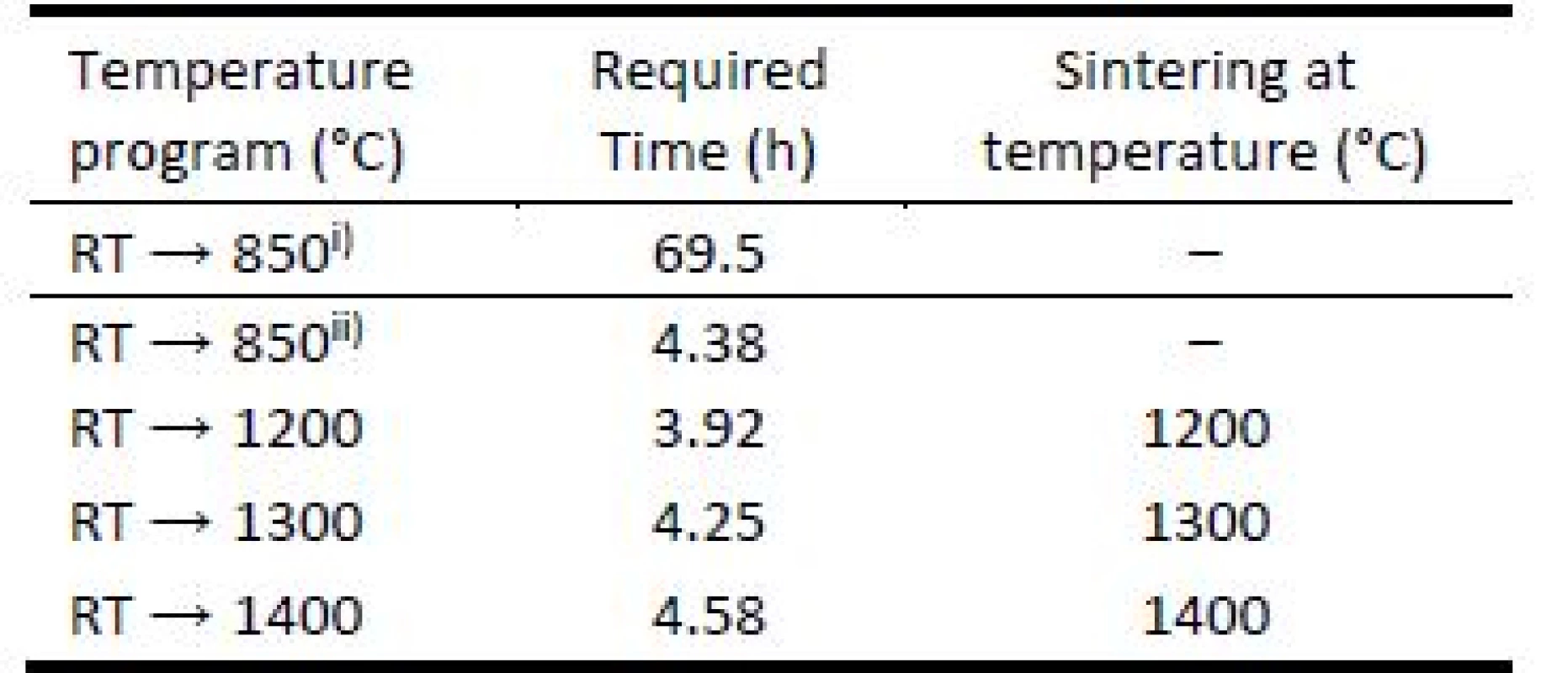
3D printed green bodies were subjected to de-binding process in laboratory furnace Clasic™ 1013 (Clasic a.s., Czech Republic), allowing programming complex heat ramp for desired heating mode. The Table 1 summarizes the temperature programs used for object debinding and sintering. The heat ramp for debinding process included was performed under slow and fast debinding modes: i) the temperature change from room temperature (RT) → 850 °C in 69.5 hours; ii) accelerated debinding from room temperature (RT) → 850 °C in 4.38 hours. The final sintering temperatures were set to 1200 °C, 1300 °C, and 1400 °C.
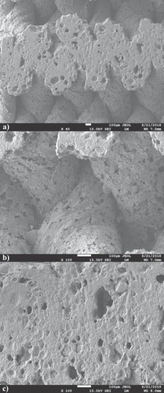
To investigate the road merging during printing and sufficiency of material coalescence in sintering process, cut segments of 3D printed bodies were inspected by scanning electron microscopy (SEM). Well merged connections of material roads are important to achieve material strength required. This investigation was done for filament filled with 65 weight % and heated to temperature 1200 °C for accelerated debinding mode. No shape-stable brown bodies were produced from filament filled with 40 weight % if the accelerated debinding mode was used.
The imaging of prepared green/brown/sintered bodies was done in accordance to magnification required, e.g. for simple printed body visualization and data archives a common camera images with resolution up to 20 MP were photographed. Magnified images for inspection of macropores were collected using optical microscope Zeiss Stemi 508. This was equipped with objective set enabling enlargements ranging from 0.63 to 5× and coupled with Axiocam 105 (Carl Zeiss AG, Germany) color camera. For inspection of mesopores SEM images of the sintered material species were recorded by a JEOL JEM-2000FX (JEOL Ltd., Tokyo, Japan) with an accelerating voltage of 160 kV.
Results
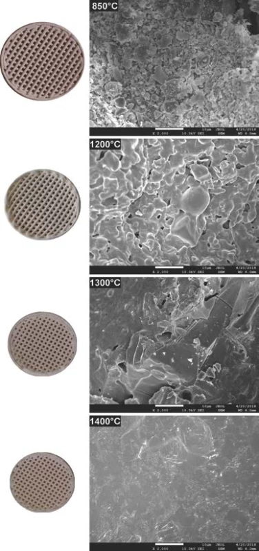
The comparison of 3D printed green body micro-structure and respective body shapes achieved from filament filled with 40 weight % and debinded in slow mode are shown in the Fig. 2. In dependence on final temperature of thermal treatment (Table 1) different surface morphology and final body shrinkage can be observed. The material merging on intercrossing sections made of filament filled with 65 weight %, debinded in fast rates and sintered at temperature 1200 °C are shown on the SEM images (Fig. 3). Single roads of crossed material can be clearly identified on the images, while magnified images show the size of several pores at the level of less than 150 µm.
In the first stage of our study, the investigation of total green body shrinkage during thermal treatment was done. Fig. 4 shows the comparison of object diameter linear shrinkage as function of debinding and sintering temperatures and ceramic pre-cursor mixture solid content. Gradual acceleration of shrinkage as tempera-ture function can be clearly identified. This indicates that processes with two rates were taking place during composite heating and differed mainly in debinding and sintering heating phases.
Discussion
The 3D printed model object debinded at 850 °C shown in Fig. 2 indicates presence of individual particles used as pre-cursor and source of aluminum oxide and silicon dioxide. Microstructure images for 1200 and 1300 °C indicate gradual reduction of the porosity resulting from the brown body structure. There is clearly observable fracture line in the right top corner of sample sintered at 1300 °C. However, the origin of this fracture is probably to be connected with sample preparation for SEM measurements, as no such fractures are to be found in the macro images corresponding to 1200 and 1400 °C. At sintering temperature of 1400 °C, only glassy surface of the ceramic objects produced from liquid phase present at this temperature can be observed. This indicates that if defined porosity for biologically applicable scaffolds is required, the sintering must be performed below temperatures where complete porosity closing is reached.
The cross sections of sample sintered to 1200 °C cut by diamond cutter shown on SEM images (Fig. 3a) demonstrate excellent material merging and homoge-neous cross-section of the roads. Nevertheless, enlarge-ment of joint material parts only does not offer clear evaluation of material merging after 3D printing and sintering (Fig. 3b). It is noteworthy, that pores observed on material sintered at temperature 1200 °C revealed presence of oval pores with sizes smaller than 150 µm required for natural bone structure mimicking. Some pores seem to be interconnected, what is essential if good level of biocompatibility of material is required (Fig. 3c) [6].
Presented results show clearly the importance of correct adjustment of several control parameters to achieve required scaffolds properties if produced by 3D printing techniques [14]. The object diameter linear shrinkage as function of debinding and sintering temperature and ceramic pre-cursor mixture solid content at the level of 40 and 65 weight % is shown in the Fig. 4. The dependence comparison noticeably indicates two stages in green body shrinkage rates during thermal treatment: i) at long debinding times, the change of shrinkage has linear dependence with the slope affected by the solid content level; ii) from certain temperature, at which the sintering of particle starts for short sintering times, the shrinkage is accelerated by increasing sintering temperature (Fig. 3). Let us define the debinding specific shrinkage rate (SRS) as change of object linear dimension change, such as diameter, divided by the time required and temperature gradient causing the change observed, by formula (1).
After debinding and their size determination were the brown bodies heated towards sintering temperature from RT by heating rate equal 5 °C per minute. In such case higher specific shrinkage rates were observed for sintering of bodies prepared from filaments having higher weight content of reacting particles. For example, higher specific shrinkage rates were found for sintering of brown bodies prepared from filament with lower solid content. ??? for heating 850 → 1400 °C and 40 weight % filament at the level of 6.942 μm∙hour–1∙°C–1, while ??? 5.504 μm∙hour–1∙°C–1 was found for 65 weight % filament. This can be seen indicative for more intensive interactions and chemical reactions between particles during ceramic body sintering from filaments with higher filling content by solid particles.The Δ? represents the object linear size change in μm which was induced in time interval dτ in hours and was caused by temperature change dt
in °C for the temperature interval RT → 850 °C and slow debinding mode. Combining the shrinkage values from Fig. 2, the time required to induce the change caused by temperature change as shown in the Table 1, we can obtain used debinding specific shrinkage rates. The bodies prepared from 40 weight % filled filament have ??? at the level of 0.087 μm∙hour–1∙°C–1. Increase of the filling solid content from 40 to 65 weight % decreased the ??? value for about the half, at the level of 0.044 μm∙hour–1∙°C–1. The debinding process is one of the most critical manufacturing steps due to its significant influence on density, shape, strength and final quality of ceramic parts produced by FDC.
Conclusions
The ceramic bodies as model objects for hard tissue replacements were prepared by FDM technology from new type of filament producing mullite type ceramics. Specific conditions for 3D production of sintered FDC parts showed favorable merging and interconnection of material roads ensuring future mechanical strength required. At the same time the porosity observed with pores < 150 µm mimics well the transport pores in real bones. As expected, it was found that overall shrinkage rates during printed body debinding and sintering are higher in case where filament with lower filling amount of ceramic pre-cursor particles was used. The debinding process is one of the most critical manufacturing steps
due to its significant influence on final quality of ceramic parts produced by FDC. Specific debinding shrinkage rate for slow debinding process was higher for filaments with lower filling grade. Similarly, higher specific shrinkage rate was found for brown bodies sintered in the temperature range 850 → 1400 °C, due to the fact that higher amount of organic binder is present in filament with lower filling grade.
Acknowledgement
The work support by research grants ITMS 26240220088, VEGA 1/0906/17 and APVV-16-0341 is greatly acknowledged.
Marián Janek, Assoc. Prof. Dr. Dipl.-Ing.
Department of Inorganic Materials
Faculty of Chemical and Food Technology
Slovak University of Technology
Radlinského 9, SK - 812 37 Bratislava
E-mail: marian.janek@stuba.sk
Phone: +421 918 674 547
Sources
- Mota C, Puppi D, Chiellini F, Chiellini E. Additive manufacturing techniques for the production of tissue engineering constructs. Journal of Tissue Engineering and Regenerative Medicine. 2012 Sep 27;9 : 174-90.
- Hwa LC, Rajoo S, Noor AM, Ahmad N, Uday MB. Recent advances in 3D printing of porous ceramics: A review. Current Opinion in Solid State and Materials Science. 2017 Aug 20;21 : 323-47.
- Seol YJ, Park DY, Park JY, Kim SW, Park SJ, Cho DW. A new method of fabricating robust freeform 3D ceramic scaffolds for bone tissue engineering. Biotechnology and Bioengineering. 2013 Jan 13;110 : 1444-55.
- Corcione CE, Scalera F, Gervaso F, Montagna F, Sannino A, Maffezzoli A. One-step solvent-free process for the fabrication of high loaded PLA/HA composite filament for 3D printing. Journal of Thermal Analysis and Calorimetry. 2018 Mar 1;134 : 575-82.
- Adel-Khattab D, Giacomini F, Gildenhaar R, Berger G, Gomes C, Linow U, Hardt M, Peleska B, Günster J, Stiller M, Houshmand A, Ghaffar KA, Gamal A, El-Mofty M, Knabe C. Development of a synthetic tissue engineered 3D printed bioceramic-based bone graft with homoge-nously distributed osteoblasts and mineralizing bone matrix in vitro. Journal of Tissue Engineering and Regenerative Medicine. 2018 Nov 9;12 : 44-58.
- Sa MW, Nguyen BN, Moriarty RA, Kamalitdinov T, Fisher JP, Kim JY. Fabrication and evaluation of 3D printed BCP scaffolds reinforced with ZrO2 for bone tissue applications. Biotechnology and Bioengineering. 2018 Dec 5;115 : 989-99.
- Thavornyutikarn B, Chantarapanich N, Sitthiseripratip K, Thouas GA, Chen Q. Bone tissue engineering scaffold-ing: computer-aided scaffolding techniques. Progress in Biomaterials. 2014 Jun 20;3 : 61-102.
- Ke X, Zhang L, Yang X, Wang J, Zhuang C, Jin Z, Liu A, Zhao T, Xu S, Gao C, Gou Z, Yan G. Low‐melt bioactive glass‐reinforced 3D printing akermanite porous cages with highly improved mechanical properties for lumbar spinal fusion. Journal of Tissue Engineering and Regen-erative Medicine. 2017 Nov 27;12 : 1149-62.
- Fielding GA, Bandyopadhyay A, Bose S. Effects of silica and zinc oxide doping on mechanical and biological properties of 3D printed tricalcium phosphate tissue engineering scaffolds. Dental Materials. 2012 Sep 16;28 : 113-22.
- Feng P, Wei P, Li P, Gao C, Shuai C, Peng S. Calcium silicate ceramic scaffolds toughened with hydroxyapatite whiskers for bone tissue engineering. Materials Charac-terization. 2014 Aug 20;97 : 47-56.
- Padmanabhan SK, Gervaso F, Carrozzo M, Scalera F, Sannino A, Licciulli A. Wollastonite / hydroxyapatite scaffolds with improved mechanical, bioactive and biode-gradable properties for bone tissue engineering. Ceramics International. 2012 Jun 23;39 : 619-27.
- Zdravkov BD, Čermák JJ, Šefara M, Janků J. Pore classification in the characterization of porous materials: A perspective. Central European Journal of Chemistry. 2007 Jan 16;5 : 385-95.
- Solano-Umaña V, Vega-Baudrit JR. Micro, Meso and Macro Porous Materials on Medicine. Journal of Bio-materials and Nanobiotechnology. 2015 October 8;6 : 247-56.
- Hollister SJ. Porous scaffold design for tissue engineer-ing. Nature Materials. 2005 Jul 1;4 : 518-24.
Labels
BiomedicineArticle was published in
The Clinician and Technology Journal

2019 Issue 1
-
All articles in this issue
- DESIGN, MANUFACTURE AND TESTING OF RABBIT IMPLANTATION STRUCTURES FOR PRECLINICAL EXAMINATIONS
- APPLICATION OF SENSORY SYSTEMS TO MOVE DOGS WITH VISUAL IMPAIRMENT
- COST ANALYSIS OF TWO TYPES OF THE LUMBAR SPINE STABILIZING SURGERY
- CERAMIC ARCHITECTURES AS MODELS FOR 3D PRINTED TISSUE ENGINEERING APPLICATIONS
- OPTIMIZATION OF ZIRCONIA INKS TO FABRICATE 3D POROUS SCAFFOLDS BY ROBOCASTING
- The Clinician and Technology Journal
- Journal archive
- Current issue
- About the journal
Most read in this issue
- OPTIMIZATION OF ZIRCONIA INKS TO FABRICATE 3D POROUS SCAFFOLDS BY ROBOCASTING
- COST ANALYSIS OF TWO TYPES OF THE LUMBAR SPINE STABILIZING SURGERY
- CERAMIC ARCHITECTURES AS MODELS FOR 3D PRINTED TISSUE ENGINEERING APPLICATIONS
- DESIGN, MANUFACTURE AND TESTING OF RABBIT IMPLANTATION STRUCTURES FOR PRECLINICAL EXAMINATIONS

